English
Greetings to the DIY Hive community as always wishing you are in the best situation and condition possible. And that if life is entertaining causing you endless setbacks and bitterness (as sometimes happens), in that case I wish you all the encouragement possible so that you can move forward.
I've been pretty busy recycling some light activated lamps, which should be easy because they have a fairly simple circuit. But the reality is that they have held up like a topsy-turvy cat after a couple of cups of coffee and donuts.
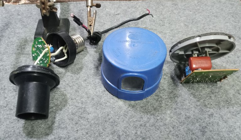
They have given me a lot of battle, one of the problems was when testing a Triac, which to put us in context I will give you the definition from Wikipedia:
“A TRIAC or triode for alternating current is a semiconductor device, from the family of thyristors. The difference with a conventional thyristor is that it is unidirectional and the TRIAC is bidirectional. In a colloquial way, it could be said that the TRIAC is a switch capable of switching alternating current "
(https://es.wikipedia.org/wiki/Triac)
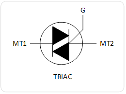
Image's Source - Fuente de la Imagen
The Triac is the electronic switch with which we can activate the relays of the electronic cards in alternating current, which we can frequently find in the electronic cards of clothes washers, motor controls, automatic lights, among other equipment.
The fact is that in this type of component it is better to test it using the voltage with which it works normally (110 volts), since if we test it with the tester we cannot use more than the 12 volts that the batteries of the fitting room. So you can have a false measurement using the tester and when the electronic component is measured using its working voltage, the component tells you if it really has a fault. (This is something I often find when checking diodes)
Well, I had to stop to make a Triac tester that was simple and worked at 110 Volts, which is the voltage of regular use for residences in my country. Those who have seen my other works know that I am dedicated to the recycling of cards and electronic equipment, So I may need to quickly measure about 10 or 15 Triacs that I have recycled from the cards that I disassemble in the week.
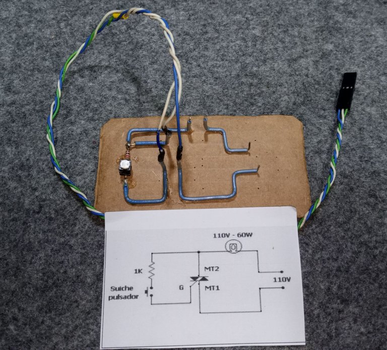
I got a pretty sober circuit at 110 Volts, on the electro-comput blog. It only required a 1K Ohm resistor (brown, black, red), a button, the three connection points to test the Triac (Mt1, Mt2, G) and an output for a 110 Volt bulb, which would be the witness. or element of the signal output.
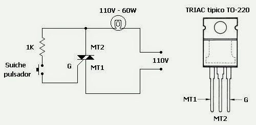
Image's Source - Image Source
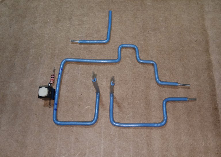
I am not going to use a bakelite board to make the circuit, the cost of bakelite is too high to spend making such a simple circuit. I wanted to do the circuit with the corrugated cardboard technique, but in the end I decided to do the circuit with the open wire technique.

It is not an electronic voodoo, as much as it seems, the circuit has not misbehaved. It is the same principle that is used in the blacksmith molds when we give the shapes to the steel bars for the construction of the bars or the internal structures for the masonry columns.

Single stranded wire works great making circuits with this open wire technique. I used led connectors and cables that I have recycled from a computer, to be able to make the test connections that I will use with the Triac.
Do not connect the indicator bulb to the output point indicated in the circuit, for now use the signal output where the bulb would go to verify the voltage output with the tester. (if I used a light bulb, the glare from the light would not have allowed me to make a good image)
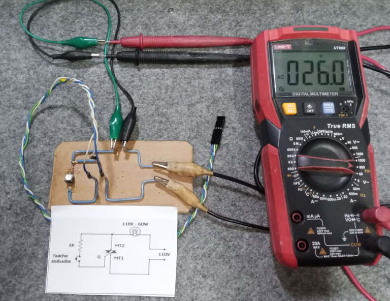
I activate the button of the test circuit and I verify the operation of the Triac, the output of the circuit when activating the button (which measures the tester) tells me that I get 120 Volts.

I fixed the circuit to a cardboard base to give it stability and the circuit is ready to help me with the recycling of components and in the repair work.
Well, thank you very much for stopping by and reading me.
The publication is not in itself a tutorial, I am only sharing the way in which I am solving the problems that appear to me in the work of the workshop.
If you are going to do any work related to electricity, remember to get trained in that area, avoid possible accidents.
Have an excellent week.
Peace.

I have used Google translate for the English language.
The images unless indicated are captures of my workshop work.
Español

Saludos a la comunidad de DIY Hive como siempre deseando que estén en la mejor situación y condición posible. Y que si la vida está entretenida causándoles un sin fin de contratiempos y amarguras (como algunas veces suele suceder), en ese caso les deseo todo el ánimo posible para que puedan salir adelante.
He estado bastante ocupado reciclando unas lámparas activadas por luz, algo que debería resultar sencillo porque tienen un circuito bastante simple. Pero la realidad es que se han defendido como un gato patas arriba después de un par de tazas de café y donas.

Me han dado bastante batalla, uno de los problemas fue al probar un Triac, que para ponernos en contexto le daré la definición de la Wikipedia:
“Un TRIAC o triodo para corriente alterna es un dispositivo semiconductor, de la familia de los tiristores. La diferencia con un tiristor convencional es que este es unidireccional y el TRIAC es bidireccional. De forma coloquial podría decirse que el TRIAC es un interruptor capaz de conmutar la corriente alterna “
(https://es.wikipedia.org/wiki/Triac)

Image's Source - Fuente de la Imagen
El Triac es el interruptor electrónico con el que podemos activar los relés de las tarjetas electrónicas en corriente alterna, que podemos hallar con frecuencia en las tarjetas electrónicas de lavadoras de ropa, control de motores, luces automáticas, entre otros equipos.
El caso es que en este tipo de componentes es mejor para probarlo usar el voltaje con el que funciona de forma corriente (110 volts), ya que si lo probamos con el tester no podemos usar más de los 12 volts que nos dan las baterías del probador. Así que puedes tener una medida falsa usando el tester y cuando el componente electrónico se mide usando su voltaje de trabajo, el componente te indica si realmente tiene una falla. (Es algo que encuentro con frecuencia cuando reviso diodos)
Pues bien, me tuve que detener para fabricar un probador de Triac, que fuese simple y trabajase en 110 Volts, que es el voltaje de uso regular para las residencias en mi país. Los que han visto de mis otros trabajos, saben que me dedico al reciclaje de tarjetas y equipos electrónicos, así que puedo tener necesidad de medir rápidamente unos 10 o 15 Triac que haya reciclado de las tarjetas que desmonto en la semana.
Conseguí un circuito bastante sobrio en 110 Volts, en el blog electro-comput. Solo se requería de una resistencia de 1K Ohm (marrón, negro, rojo), un pulsador, los tres puntos de conexión para probar el Triac (Mt1, Mt2, G) y una salida para un bombillo de 110 Volt, que sería el testigo o elemento de la salida de señal.
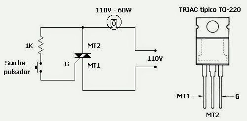
Image's Source - Fuente de la Imagen
No voy a usar una placa de baquelita para hacer el circuito, el costo de la baquelita es muy alto como para gastarlo haciendo un circuito tan sencillo. Quería hacer el circuito con la técnica del cartón corrugado, pero al final me decidí por hacer el circuito con la técnica del cable al aire.

No es un vudú electrónico, por mucho que lo parece, el circuito no se ha portado mal. Es el mismo principio que se usa en los moldes de herrería cuando le damos las formas a las barras de acero para construcción de las rejas o las estructuras internas para las columnas en albañilería.

El cable de un solo hilo queda muy bien haciendo circuitos con esta técnica de cable al aire. Use conectores y cables para led que he reciclado de un computador, para poder hacer las conexiones de prueba que usaré con el Triac.

No conecte el bombillo testigo en el punto de salida indicado en el circuito, de momento use la salida de señal donde iría el bombillo para verificar la salida de voltaje con el tester. (si usaba un bombillo, el resplandor de la luz no me habría dejado hacer una buena imagen)

Activo el pulsador del circuito de prueba y verifico el funcionamiento del Triac, la salida del circuito al activar el pulsador (que mide el tester) me indica que obtengo los 120 Volts.

Fije el circuito a una base de cartón para darle estabilidad y ya queda el circuito listo para ayudarme al reciclaje de componentes y en los trabajos de reparación.
Bien, muchas gracias por pasar y leerme
La publicación no es en sí un tutorial, solo les comparto la forma en que voy resolviendo los problemas que se me presentan en el trabajo del taller.
Si van a realizar algún trabajo relacionado con la electricidad, recuerden capacitarse en esa área, eviten posibles accidentes.
Que tengan una excelente semana.
Paz.

He usado el traductor de Google para el idioma inglés.
Las imágenes a menos que lo indique son capturas de mi trabajo de taller.


