ESPAÑOL
Los protectores de voltaje son aparatos electrónicos que se encargan de velar el voltaje de la red eléctrica, detectando cualquier variación del voltaje que salga del rango para el cual está calculado el circuito del protector, ya sea por bajo voltaje o alto voltaje, el mismo desconecta la carga (equipo protegido) hasta que desaparezca la condición de alto o bajo voltaje, acto seguido entra en modo espera durante un tiempo determinado hasta volver a conectar la carga.
Estas variaciones suelen aparecer durante los apagones, interrupciones momentáneas, parpadeos (Flicker), tormentas eléctricas, etc. Es por ello que es indispensable proteger nuestros equipos más sensibles a estas variaciones y para ello se emplean estos protectores de voltaje. Hoy les mostraré la reparación de uno en específico que dejó de funcionar después de habérsele caído accidentalmente a su dueño.
El GSM-RE-120 es un protector de voltaje para refrigerador y aires acondicionados de 120 Volts, con un voltaje máximo fijo permitido de 140 Volts, un voltaje mínimo ajustable que va desde los 90 - 105 Volts y una perilla de ajuste del voltaje mínimo.
Esto quiere decir que mientras el voltaje de la red eléctrica se encuentre entre el voltaje mínimo ajustado y 140 Volts, la carga estará conectada. Si existe una variación por debajo o por encima de este rango, automáticamente se desconectará la carga (Refrigerador, nevera, aire acondicionado, etc.)
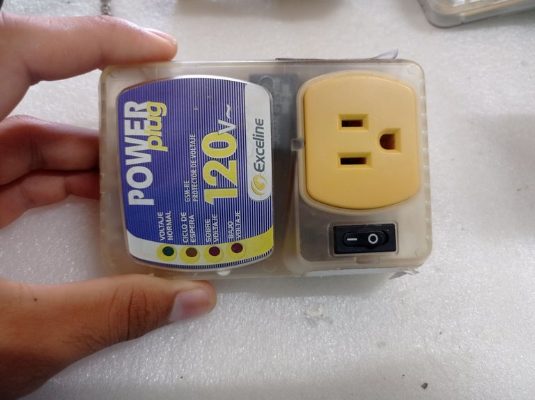
Protector de voltaje GSM-RE120
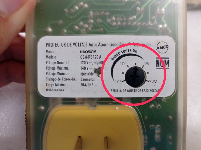
Perilla de ajuste de bajo voltaje
Este protector mostraba un síntoma en el que aparentemente todo funcionaba correctamente, mostraba a través del LED amarillo su ciclo de espera y al concluir este, se activaba el LED verde que indica que el voltaje está en parámetros, sin embargo a pesar de estar encendido el LED verde, no existía Voltaje a la salida del protector.
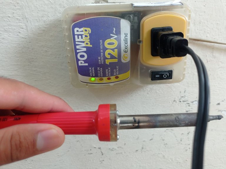
Cautín apagado a pesar de que el protector tiene el LED verde encendido
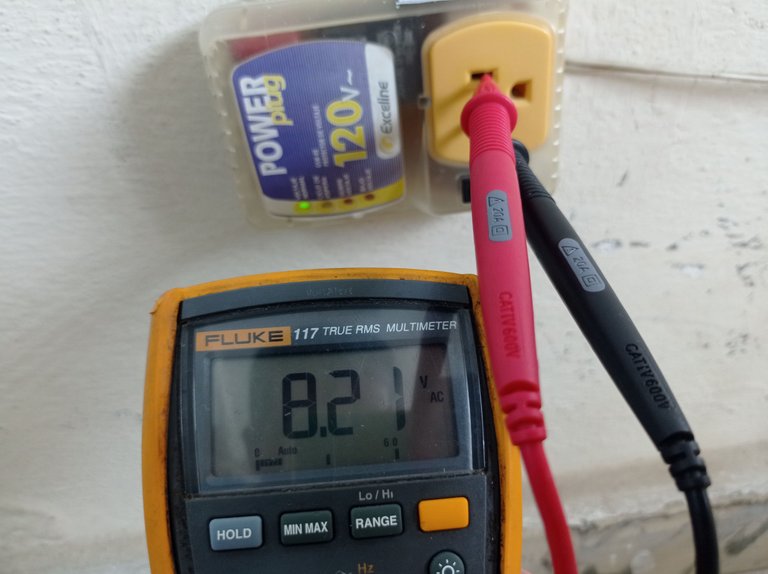
Al medir la salida del protector con el multímetro se observa que solo marca 8 volt, lo que demuestra que no hay voltaje de la red eléctrica a la salida
Una de las causas de este síntoma en los protectores suele ser producto de una o varias caídas, como sucedió en este caso en particular.
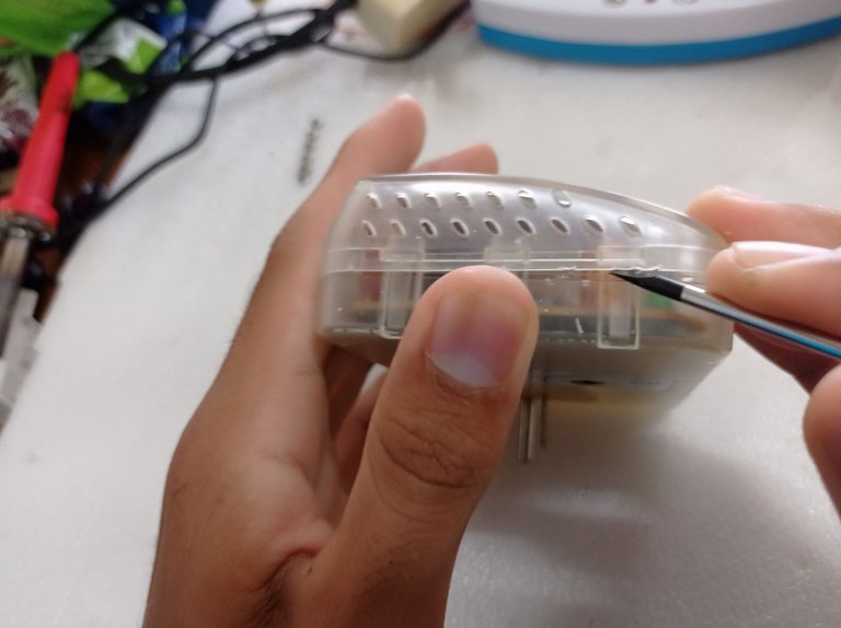
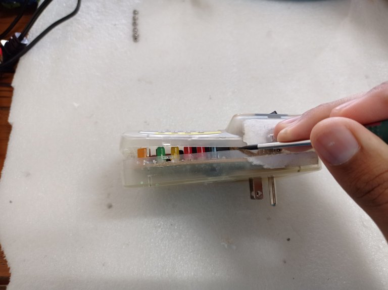
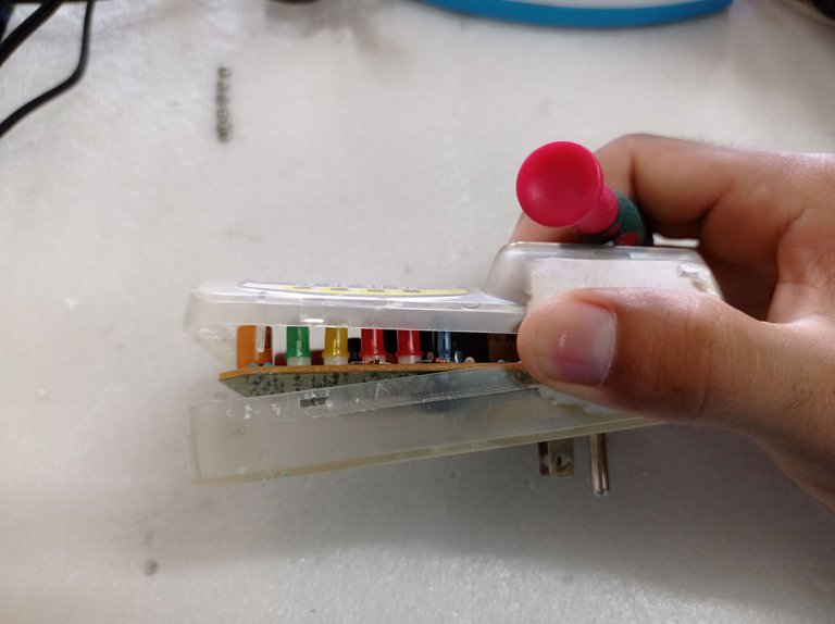
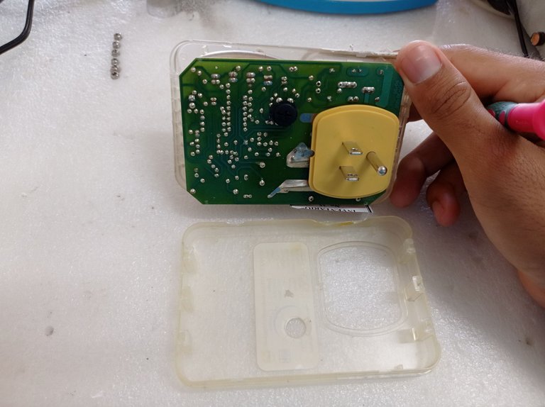
Cuando esto sucede lo primero que debemos hacer es abrir el protector, en este caso no tiene tornillos, basta con hacer palanca con un destornillador por los bordes para separar las dos piezas de la carcasa que están unidas a través de presillas plásticas.
Funcionamiento del circuito
Al abrir el protector se pueden apreciar sus componentes, y a simple vista se observa lo que sería el corazón del circuito, que en este caso es el integrado LM339 que no es más que un comparador de voltaje cuádruple que cuenta en su interior con cuatro amplificadores operacionales funcionando como comparadores.
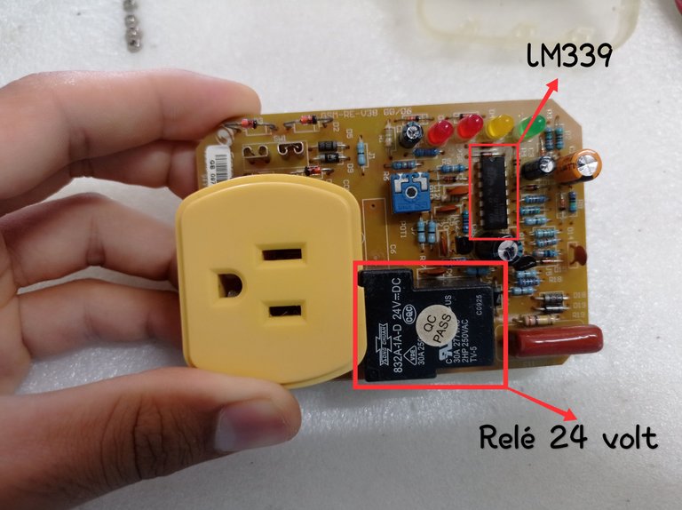
Placa electrónica del protector GSM-RE-120 en el que se señalan el integrado LM339 y el Relé de 24 Volts
Estos amplificadores operacionales a grandes rasgos se encargan de comparar una muestra del voltaje de la red eléctrica, aplicada a una de sus dos entradas a través de resistencias formando divisores de tensión, este sería el voltaje de entrada (Vin). Al mismo tiempo, este Vin es comparado con un voltaje de referencia (Vref), fijado en la otra entrada del amplificador operacional, A la salida de los operacionales existirá un valor alto o bajo en función de la comparación de los Voltajes. Vin y Vref.
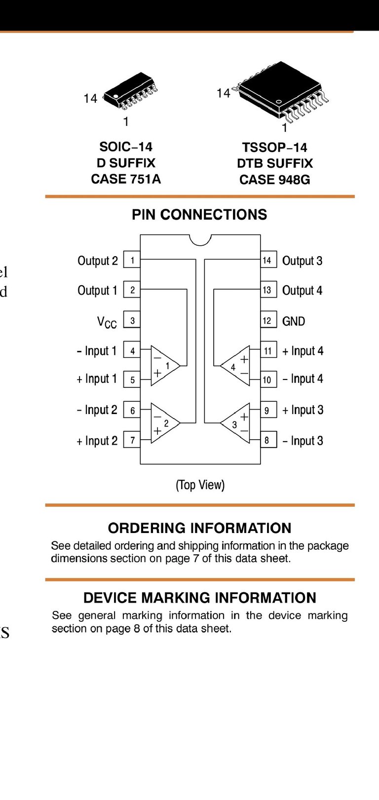
Representación del integrado LM339, con sus cuatro amplificadores operacionales internos, Entradas por los pines 4-5, 6-7, 8-9 y 10-11. Salidas por los pines 1, 2, 13 y 14.
El resultado de la comparación está determinada por el voltaje en la red eléctrica y mientras no sobrepase los 140 volts ni caiga por debajo del valor mínimo fijado (90-105 volts) uno de los amplificadores operacionales activará un transistor que funciona como interruptor, permitiendo que se energice con 24 Volts de corriente directa el inductor del relé, lo que provoca que se unan en su interior los contactos que cierran el camino de la corriente hacia la salida del protector. El colega @profwhitetower trata el tema de los amplificadores operacionales, su funcionamiento y diferentes configuraciones en varias publicaciones que podrás ver en su blog si es de tu interés este tema.
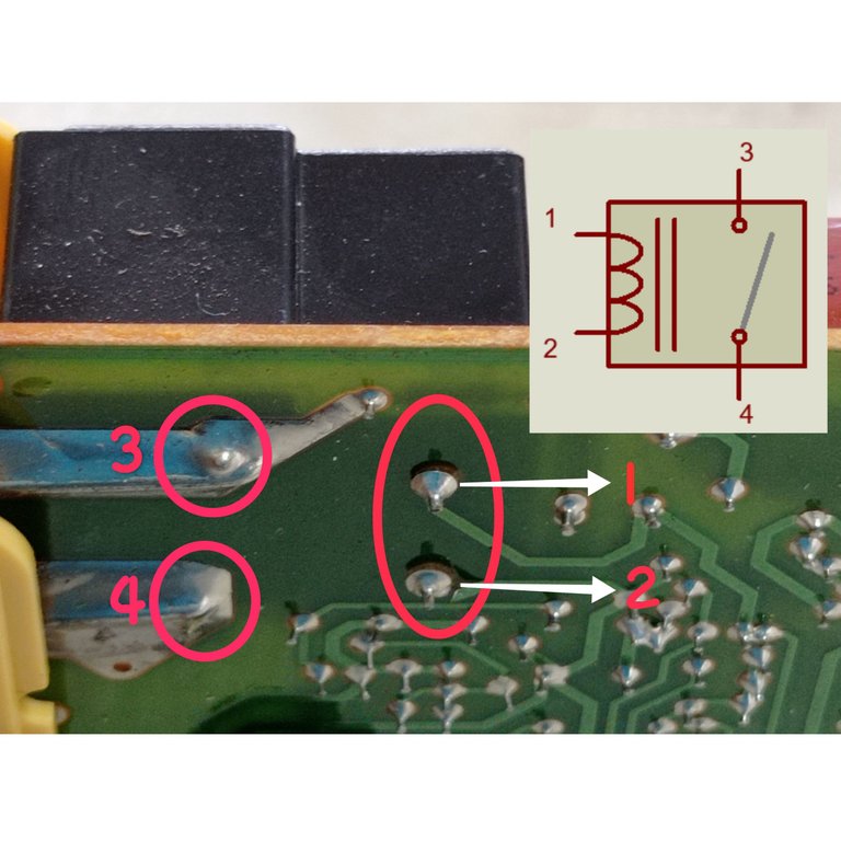
Representación de los pines del relé, entre 1 y 2 se encuentra la bobina, 3 y 4 son los contactos que deben unirse internamente para permitir la presencia de voltaje a la salida del protector
Encontrando la causa de la falla.
Al inicio del post comenté que el protector sufrió una caída y que acto seguido dejó de funcionar, este es un dato importante porque nos da una idea de lo que pudiera haber sucedido. Cuando estos aparatos caen desde cierta altura el golpe tiende a deformar o quebrar las uniones de los pines con las pistas de cobre, particularmente las uniones de los componentes más pesados, que al caer ejercen mayor tensión sobre la placa producto al golpe, es por ello que lo primero que se debe hacer es realizar la inspección ocular minuciosamente de la placa en busca de roturas o soldaduras frías en los pines de los componentes, empezando por los más grandes y pesados. En el protector el componente más grande y pesado es el relé, por lo que al inspeccionar sus conexiones no fue difícil apreciar que las uniones de los pines de la bobina (1 y 2) se encontraban partidas debido a la caída. Este problema impedía que los 24 volts fueran aplicados a la bobina y por tanto el relé nunca se activaba , evitando así la unión de sus contactos internos, por lo que no existía salida de voltaje.
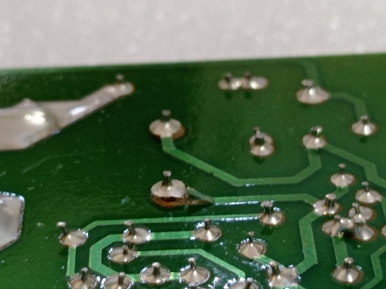
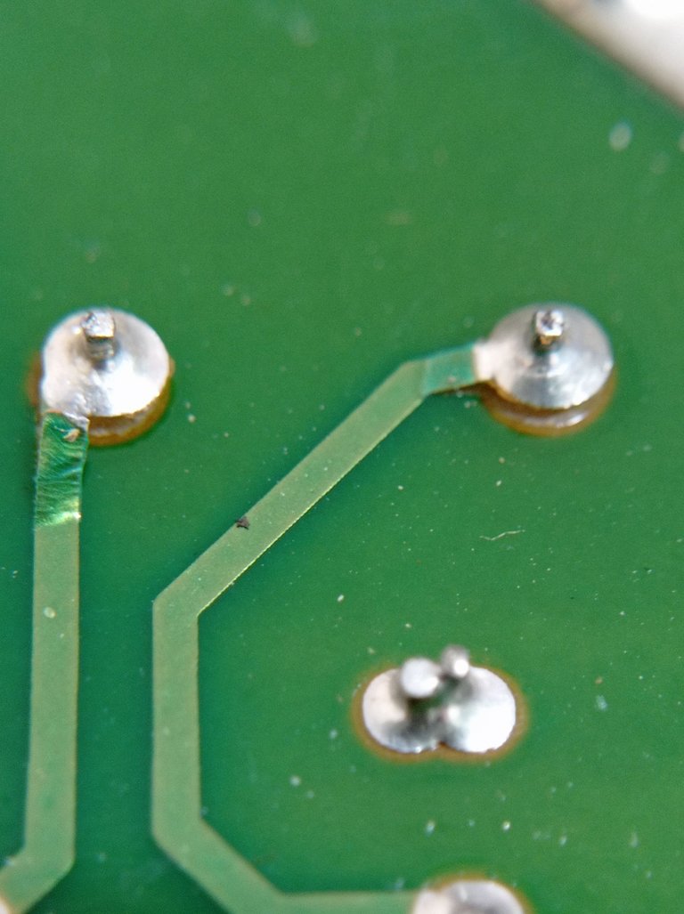
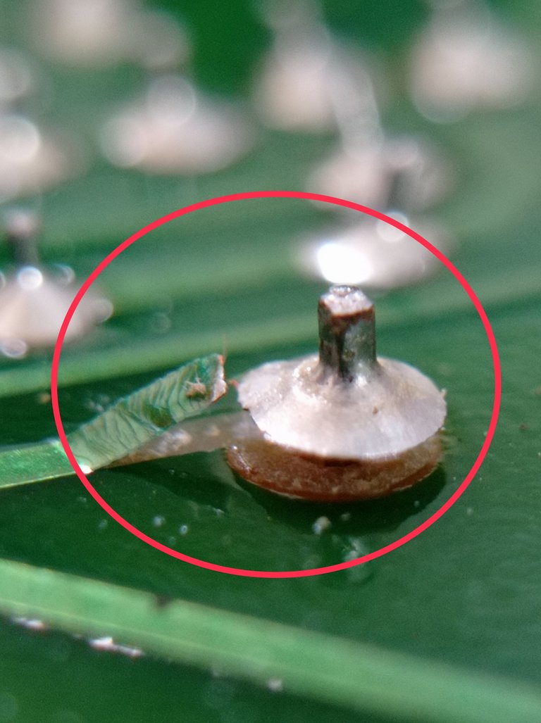
Pistas de cobre destruidas en las uniones de los pines del relé, debido a la caída
Cómo se aprecia claramente en las imágenes anteriores, la solución a la causa de la falla consiste en reconstruir nuevamente estas pistas de cobre y aplicar una soldadura con ayuda del cautín.
Reparando las pistas destruidas.
Para solucionar el problema primeramente se deben raspar las pistas con el objetivo de quitarle el esmalte aislante. Con mucho cuidado de no dañar más aún la pista, fui raspando poco a poco el esmalte aislante con ayuda de un destornillador de punta plana y con cierto nivel de filo, hasta lograr ver la superficie de cobre de la pista.
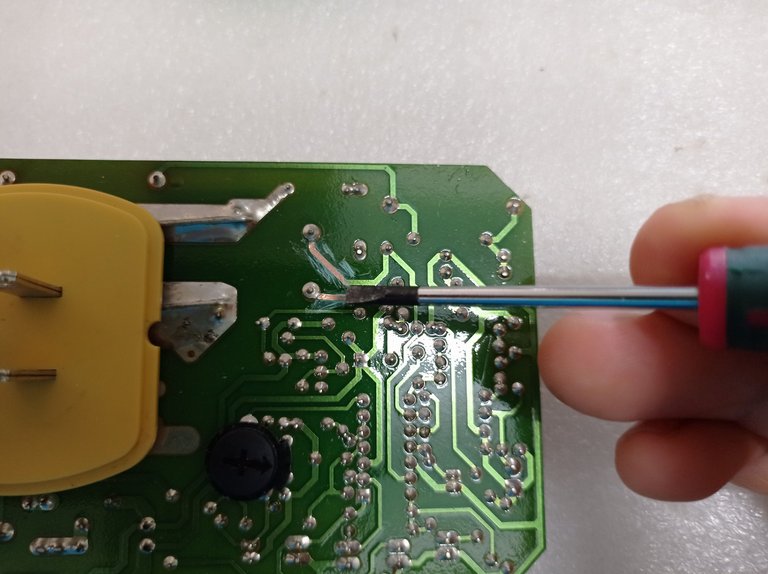
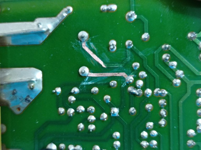
Quitar el esmalte de las pistas de cobre
El siguiente paso será reconstruir las pistas con ayuda de un alambre fino de cobre, yo he reciclado uno de los alambres de los pares trenzados de los cables para telecomunicaciones, muy similares a los que utilizan los cables de red Ethernet. Utilicé un trozo de este alambre, le apliqué un baño de estaño para posteriormente reconstruir la pista. En las siguientes imágenes se muestra el proceso
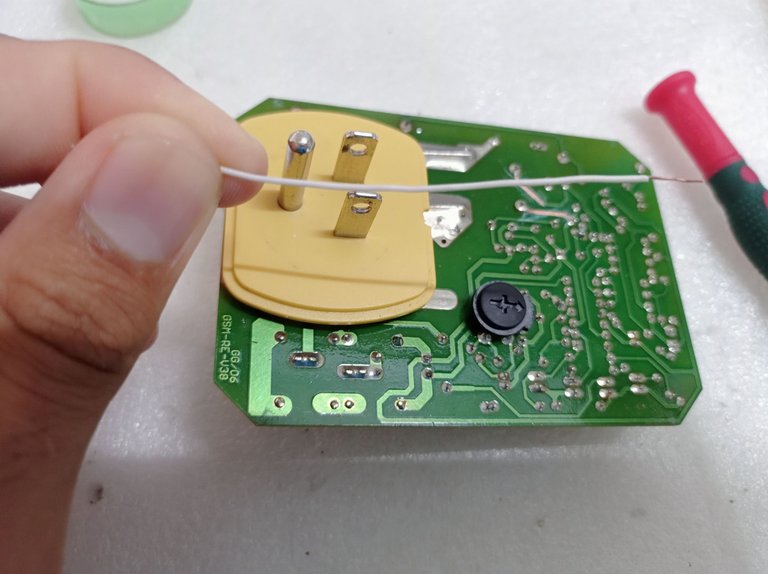
Alambre reciclado para reconstruir las pistas
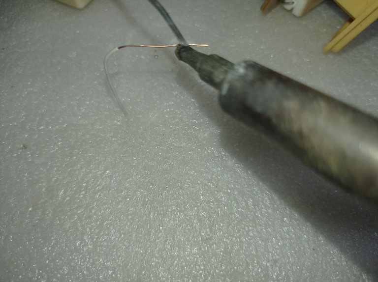
Bañar el alambre en estaño con ayuda del cautín
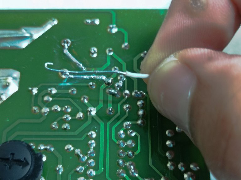
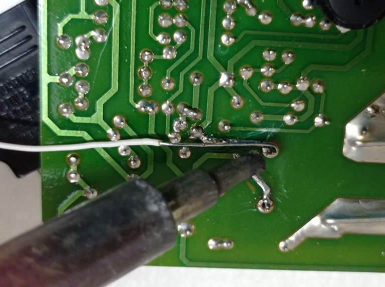
Soldar el alambre al pin del relé y a la pista
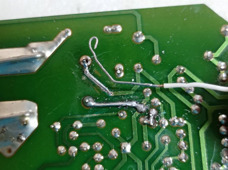
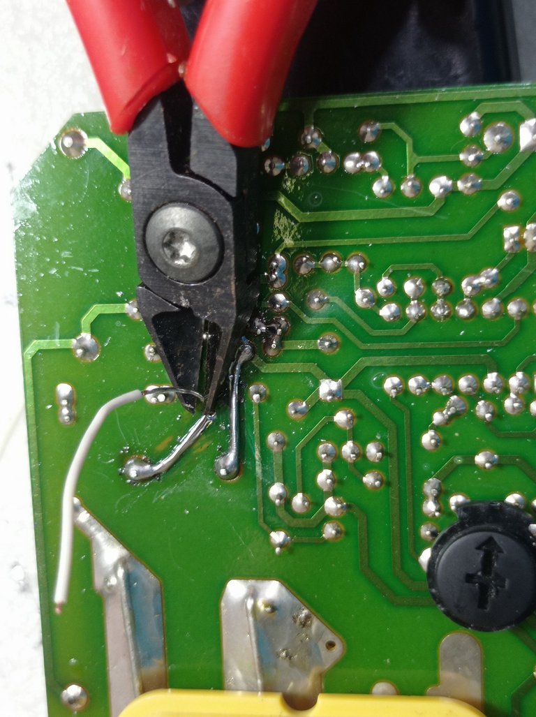
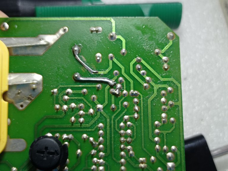
Pistas reconstruidas
Resultados finales.
Después de reconstruir las pistas lo siguiente fue realizar nuevamente la medición con el multímetro en la escala de voltaje de corriente alterna (AC).
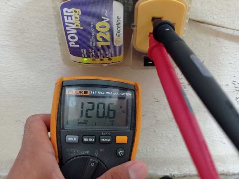
Medición del voltaje de salida del protector después de corregida la causa de la falla. Salida de 120 volt de AC.
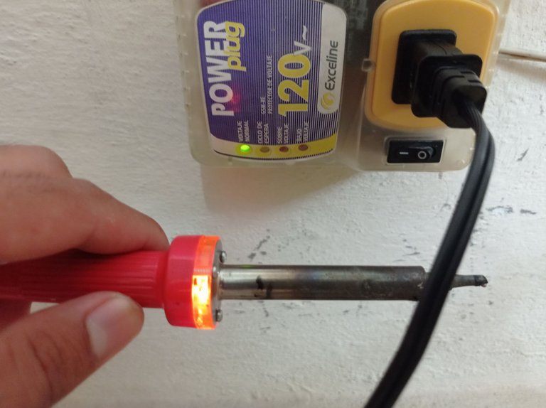
Esta vez el cautín funciona al conectarlo al protector, se aprecia la iluminación del bombillo indicador
La avería descrita anteriormente es común y fácil de reparar por nosotros mismos en casa, en ocasiones recurrimos a otras personas que no siempre son justos en el cobro de una reparación como esta, y terminamos siendo víctimas de un atropello. Si decides hacer tus propias reparaciones a este tipo de protectores de voltaje, recuerda tomar todas las medidas pertinentes y trabajar siempre con el circuito desconectado de la red eléctrica para evitar accidentes por choques eléctricos.
Saludos y hasta la próxima 😉
Las fotos fueron tomadas con el celular Xiaomi Redmi Note 9 y la portada editada en Canva
Puedes verme en Facebook
ENGLISH
Voltage protectors are electronic devices that are responsible for monitoring the mains voltage, detecting any voltage variation outside the range for which the protector circuit is calculated, either by low voltage or high voltage, it disconnects the load (protected equipment) until the high or low voltage condition disappears, then enters standby mode for a certain time until reconnecting the load.
These variations usually appear during blackouts, momentary interruptions, flicker, electrical storms, etc. That is why it is essential to protect our most sensitive equipment to these variations and for this purpose these voltage protectors are used. Today I will show the repair of a specific one that stopped working after having accidentally fallen to its owner.
The GSM-RE-120 is a voltage protector for 120 Volt refrigerator and air conditioners, with a fixed maximum allowable voltage of 140 Volts, an adjustable minimum voltage ranging from 90 - 105 Volts and a minimum voltage adjustment knob.
This means that as long as the mains voltage is between the set minimum voltage and 140 Volts, the load will be connected. If there is a variation below or above this range, it will automatically disconnect the load (refrigerator, fridge, air conditioner, etc.).

GSM-RE120 Voltage Protector

Low voltage adjustment knob
This protector showed a symptom in which apparently everything was working correctly, showed through the yellow LED its standby cycle and at the end of this, the green LED was activated indicating that the voltage is in parameters, however despite the green LED was on, there was no voltage at the output of the protector.

Cautín off even though the protector has the green LED on

When measuring the output of the protector with the multimeter, it only shows 8 volts, which proves that there is no mains voltage at the output.
One of the causes of this symptom in the protectors is usually the result of one or more falls, as happened in this particular case.
When this happens the first thing to do is to open the protector, in this case it does not have screws, just pry it with a screwdriver along the edges to separate the two pieces of the housing that are joined by plastic clips.


Circuit operation
When the protector is opened, its components can be seen, and at a glance you can see what would be the heart of the circuit, which in this case is the LM339 integrated which is nothing more than a quad voltage comparator that has inside four operational amplifiers working as comparators.

Electronic board of the GSM-RE-120 protector showing the integrated LM339 and the 24 Volt relay.
These operational amplifiers are in charge of comparing a sample of the mains voltage, applied to one of its two inputs through resistors forming voltage dividers, this would be the input voltage (Vin). At the same time, this Vin is compared with a reference voltage (Vref), set at the other input of the operational amplifier. At the output of the op-amps there will be a high or low value depending on the comparison of the voltages. Vin and Vref.

Representation of the LM339 integrated, with its four internal operational amplifiers, Inputs on pins 4-5, 6-7, 8-9 and 10-11. Outputs on pins 1, 2, 13 and 14.
The result of the comparison is determined by the mains voltage and as long as it does not exceed 140 volts or fall below the minimum set value (90-105 volts) one of the operational amplifiers will activate a transistor that works as a switch, allowing the relay inductor to be energized with 24 Volts of direct current, which causes the contacts that close the current path to the output of the protector to be joined inside. The colleague @profwhitetower deals with the subject of operational amplifiers, their operation and different configurations in several publications that you can see in his blog if you are interested in this topic.

Representation of the relay pins, between 1 and 2 is the coil, 3 and 4 are the contacts that must be connected internally to allow the presence of voltage at the output of the protector.
Finding the cause of the failure.
At the beginning of the post I mentioned that the protector suffered a fall and then stopped working, this is an important piece of information because it gives us an idea of what could have happened. When these devices fall from a certain height, the blow tends to deform or break the joints of the pins with the copper tracks, particularly the joints of the heavier components, which when falling exert greater stress on the board due to the blow, which is why the first thing to do is to perform a thorough eye inspection of the board in search of breaks or cold soldering on the pins of the components, starting with the largest and heaviest ones. In the protector the largest and heaviest component is the relay, so when inspecting its connections it was not difficult to see that the coil pin junctions (1 and 2) were split due to the drop. This problem prevented the 24 volts to be applied to the coil and therefore the relay was never activated, thus preventing the union of its internal contacts, so there was no voltage output.


Copper tracks destroyed at the relay pin junctions, due to dropping
As can be clearly seen in the images above, the solution to the cause of the failure consists of rebuilding these copper tracks again and applying solder with the aid of the soldering iron.
Repairing the destroyed tracks.
To solve the problem, the tracks must first be scraped to remove the insulating enamel. Being very careful not to damage the track even more, I scraped the insulating enamel little by little with the help of a flat tip screwdriver and with a certain level of sharpness, until I could see the copper surface of the track.


Removing enamel from copper tracks
The next step will be to rebuild the tracks with the help of a thin copper wire, I recycled one of the wires of the twisted pairs of telecommunication cables, very similar to those used in Ethernet network cables. I used a piece of this wire, applied a tin bath to it and then reconstructed the track. The following images show the process.

Recycled wire to rebuild the tracks.

Dip the wire in tin with a soldering iron.


Solder the wire to the relay pin and to the track.


Rebuilt tracks
Final results.
After reconstructing the tracks, the next step was to measure again with the multimeter on the AC voltage scale.

Measurement of the protector output voltage after the cause of the fault has been corrected. 120 volt AC output.

This time the soldering iron works when connected to the protector, the indicator light bulb illumination is visible.
The breakdown described above is common and easy to repair by ourselves at home, sometimes we resort to other people who are not always fair in charging for a repair like this, and we end up being victims of an outrage. If you decide to make your own repairs to this type of voltage protectors, remember to take all the relevant measures and always work with the circuit disconnected from the mains to avoid accidents due to electric shocks.
Greetings and see you next time. 😉
The photos were taken with the Xiaomi Redmi Note 9 cell phone and the cover was edited in Canva.
Text translated to English in Deepl translator.
You can see me at Facebook


